
Connecting a Receiver to your Turntable
Connectors (Left to Right)
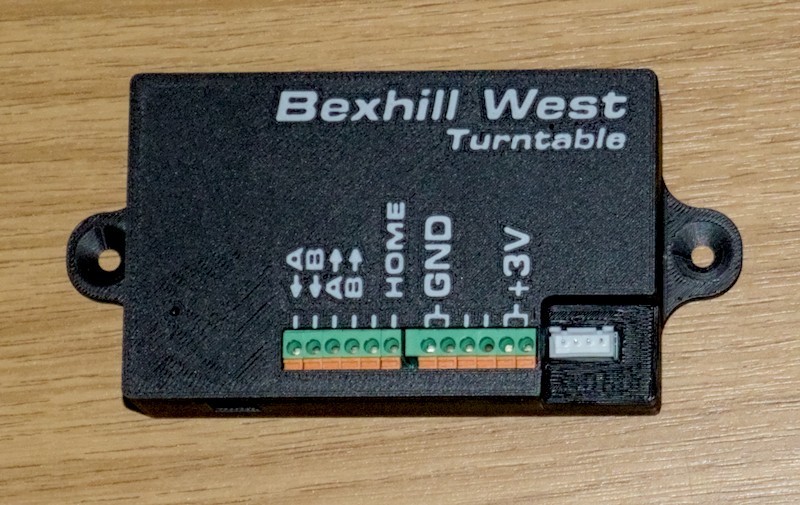
From left to right, the connectors on the Turntable Receiver unit are:
- 9-36V DC jack (on the side face, not on the top), 2.5mm barrel jack, centre positive.
- 12V is the recommended value.
- Using an appropriate adapter, you can connect any suitable DC supply to your receiver unit.
Please do not connect DCC track power directly to the power inlet! Doing so could seriously damage your receiver unit!
- The 12 terminal block connections; the ones in use are labelled:
- 1 - Track Power In (rail A)
- 2 - Track Power In (rail B)
- 3 - Track Power out (rail A)
- 4 - Track Power out (rail B)
- 5 - Not currently used
- 6 - Home sensor signal
- 7 and 8 - Ground (0v)
- 9 and 10 - Not currently used
- 11 and 12 - +3 volts
The +3v and Ground wires should be used to power the home sensor. The Home sensor signal is connected to terminal 6. If you have purchased a Bexhill West Universal Drive Unit, this is fitted with an optical sensor which can be connected directly. The system is also compatible with hall (magnetic) switches (e.g. AH3582-P-B).
To power the rails on your turntable bridge, you can connect the track power A & B inputs to your DC or DCC supply, and the A & B outputs to the wires that emerge from the slip ring connector on the drive unit. These are straight pass-through connections, with an internal changeover relay to swap the polarity as required (see the programming section for more details).
To connect to the terminal block, you will need a small jeweller's style screwdriver: Push down on the orange lever to insert the wire, then release the pressure. The wire should be gripped firmly - test by gently pulling on it. If it pops straight out, just try again. To release a wire, simply push down on the orange lever again, and pull the wire out. You may need to jiggle it a bit to free it off. This works best if the receiver is sitting on a nice flat surface, or if you have at least three hands...
- Stepper Motor connector
The final connection is for the stepper motor - this is for a standard 4-pin JST connector, as typically supplied with any bipolar stepper motor. We recommend the use of a NEMA-17 sized motor, if you were not supplied with one. For example, this one.
If, when you power up your unit, the stepper buzzes and/or jitters instead of moving smoothly, you may need to change the order of the wires in the connector. If this happens to you, please reach out to us so I can add a detailed "how to" guide to this manual
The plug will only fit one way.
Factory Reset
Should you, for any reason, need to carry out a full reset of the receiver unit - there is a small hole to the left of the terminal block:
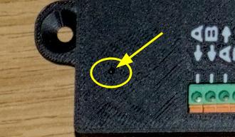
- Power off the receiver
- Insert the end of a bent paperclip (or similarly thin object) into the hole, until you feel/hear a "click".
- Holding the paperclip in position, power up the receiver.
- After about 5 seconds, release the paperclip. The receiver will re-boot having cleared all its original settings
If you change your turntable drive gear ratio (calibration), you will need to factory reset the unit, otherwise it will not rotate the correct distances. If you wish to pair a receiver with your controller, and the original controller to which it was paired is not available, it will require a factory reset. We would also suggest you carry this procedure out if you sell a used receiver, or purchase a used receiver.
Firmware Updates
From time to time, as we identify bugs or new functions which can be accommodated by the hardware, we will issue firmware updates. There is a Micro-USB port on the left hand side of the unit which will be used to accomplish this. This port should not be used for any other purpose - except for one: If you look into the hole, there will be a red light visible if the unit is powered on.