
Bogie design
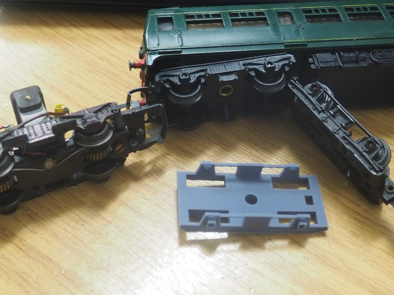
Pictured above is a later Triang DMU, with its front dummy bogie riveted in place, and the power bogie removed, showing the motor sticking up vertically. To the right is an older Triang dummy bogie, on which the replacement (front) is based. At this time, I'm not sure which is the most prototypical; I suspect the newer one, so I'll probably amend the design to that. Or a more accurate one, if I can find one.
I've started with the dummy bogie; the power bogie will be adapted from this design in the near future. The main jobs outstanding are:
- Finish adding the side details (springs, rivets and so on)
- Add a NEM pocket at the correct height
- Amend design to fit a coreless motor with dual worms
- Add power pickups
- Figure out how to mount it in the body (and what modifications may be needed to the body to enable this)
- Buy Alan Gibson wheelsets & convert to driven axles by adding worm gears
There's likely to be other challenges along the way.... One of the biggest will be how to fit the entire motor drive assembly underneath the existing chassis.
For the rear bogie, I have options: The dummy car has a flat plate with a plain bogie riveted to it, which can be re-designed to allow for some incursion into the body shell (hopefully without compromising the interior - although the original Triang interior stops short of the motor bogie, due to its height. The dummy bogie plate is held in place by the under body detail, this is likely to need changing.
The front bogie is more difficult; this is fitted to a moulded section of floor in the body shell. It's likely that some of this floor pan will need to be hacked away, in order to fit the new front drive motor bogie. After that, it should be pretty similar to the rear bogie.
Perhaps the most tricky part will be to figure out how to mount both bogies in such a way that they can freely pivot as required. As of yet, I do not have a design for this...
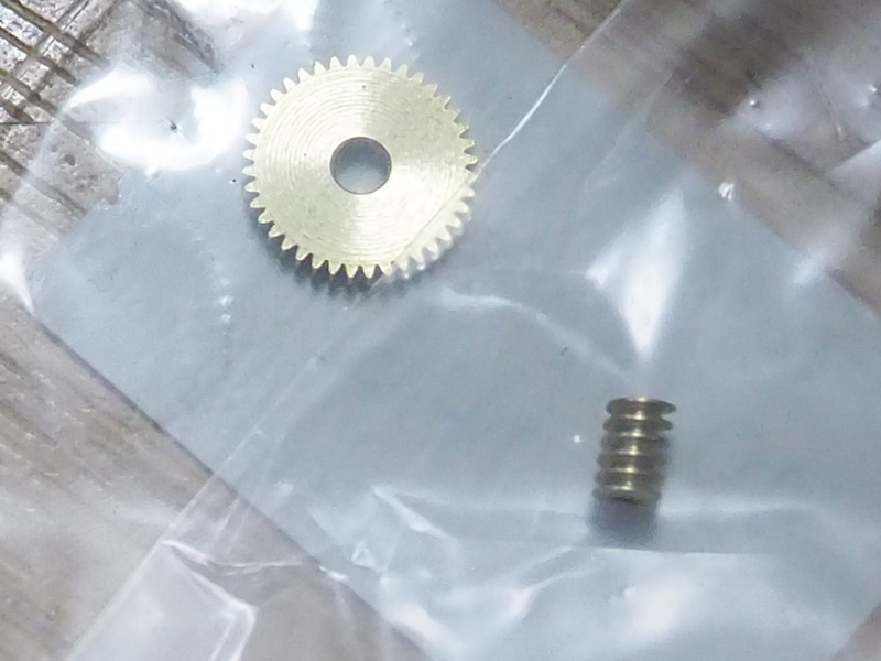
Above picture shows the drive gears. They are absolutely tiny - for reference, the centre hole of the worm wheel is 2mm; the worm itself is only about 2mm across. They are Module 0.2 (i.e. 5 teeth per millimetre). The pictured gear has 40 teeth - however, my calculations suggest that with an 18,000rpm motor, this will give a scale speed of slightly under 50mph: Therefore I may yet use a gear with fewer teeth - 32 might be a good compromise (giving a scale speed of nearly 60mph). the smaller gear will also allow the motor to be mounted fractionally lower, which could help with bodyshell clearance and incursion.
No Comments